
Triumph 650 Ignition Timing Illustrated
The following ignition timing procedures are for 1968 and later Triumph 650
unit twins using Lucas contact breaker 6CA (primary backplate and two
secondary plates), OR, a machine whose 4CA contact breaker was upgraded to 6CA..
If you're setting ignition timing on a 1963-67 Triumph Twin using the 4CA points/contact breaker plate assembly, follow this excellent tutorial by Don on TriumphRat.net.
Contact Breaker Photos
Contact breaker photos at the beginning of the static and dynamic timing sections are identical. They are repeated for your viewing convenience.
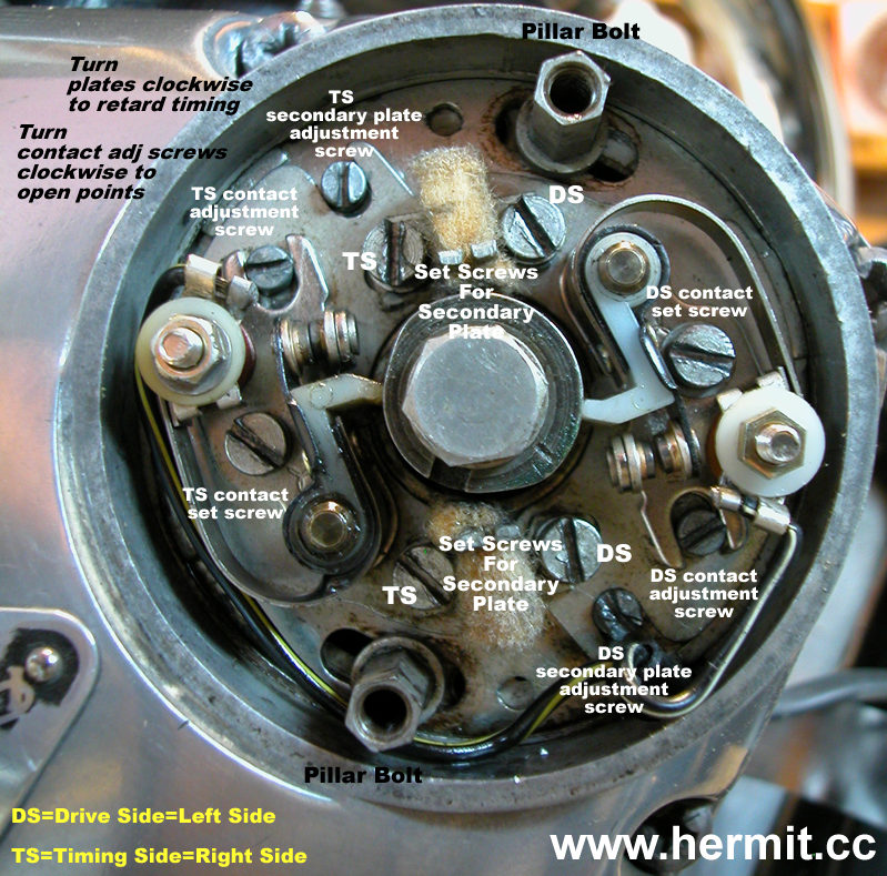
Identification of set screws and adjustment screws
Initial (static) timing setup (Hancox)
- Remove spark plugs and engage 4th gear
- Remove points cover
- Center back plate
- Loosen pillar bolts and rotate back plate until the pillar bolts are centered in the back plate's slots
- Re-tighten pillar bolts
- Set contact point gaps
- Rotate engine until heel of DS points arm is just past the high point on the cam, i.e. to the line. Points are now fully open
- Set points gap to .015"
- Rotate engine 360 degrees and set TS points to .015"
- Set static timing for first point set
- Locate TDC using chop stick in spark plug hole
- Install D1859 flywheel locator body
- Insert plunger and gently rock rear tire in gear until plunger drops
This is the second hole in the flywheel (exact TDC)
- Remove plunger and rotate rear tire backwards very slightly
- Replace plunger
- Continue rotating tire backwards until plunger drops
This is the first hole in flywheel (38 degrees before TDC)
- Adjust points which are closed and just opening
- Push and hold cam shaft clockwise with screwdriver
Opens Auto-Advance assembly fully
- Slacken secondary plate set screws for closed/opening points
- Hold points open with screwdriver and insert small piece of rolling paper
- Use plate adjustment screw to adjust points until rolling paper pulls out (.0015")
- Re-tighten secondary plate set screws
- Re-check to see that paper pulls out
- Remove plunger
- Set static timing for second point set
- With plunger removed, rotate engine 360 degrees
- Locate TDC using chop stick in spark plug hole
- Insert plunger and gently rock rear tire in gear until plunger drops
This is the second hole in the flywheel (exact TDC)
- Remove plunger and rotate rear tire backwards very slightly
- Replace plunger
- Continue rotating tire backwards until plunger drops
This is the first hole in flywheel (38 degrees before TDC)
- Adjust the second set of points, those which are now closed and beginning to open
- Push and hold cam shaft clockwise with screwdriver
Opens Auto-Advance assembly fully
- Slacken secondary plate set screws for closed/opening points
- Hold points open with screwdriver and insert small piece of rolling paper
- Use plate adjustment screw to adjust points until rolling paper pulls out (.0015")
- Re-tighten secondary plate set screws
- Re-check to see that paper pulls out
- Remove plunger
- Remove D1859 flywheel locator body and replace spark plugs
Identification of set screws and adjustment screws
Dynamic timing
After initial timing setup, set dynamic timing using a stroboscope. Note
the following:
- Rotating the primary plate or a secondary plate clockwise
causes the strobed timing mark to move counterclockwise (retards timing),
for one cylinder (secondary plate), or both cylinders (primary backplate)
- Rotating the primary plate or a secondary plate counterclockwise
causes the strobed timing mark to move clockwise (advances timing)
for one cylinder (secondary plate), or both cylinders (primary backplate)
TS cylinder
- Hook up stroboscope to external 12v battery and TS sparkplug
- Loosen TS secondary plate set screws (left-hand side)
- Start engine
- Using TS secondary plate adjustment screw, adjust timing mark
to conincide with timing pointer at 2,000 RPM
- Re-tighten secondary plate set screws
- Re-check timing
Note: if there is not enough adjustment using the secondary plate adjustment
screw, loosen pillar posts and rotate the primary backplate until correct
timing is acheived
DS cylinder
- Hook up stroboscope to external 12v battery and DS sparkplug
- Loosen DS secondary plate set screws (right-hand side)
- Start engine
- Using DS secondary plate adjustment screw, adjust timing mark
to conincide with timing pointer at 2,000 RPM
- Re-tighten secondary plate set screws
- Re-check timing
Note: if there is not enough adjustment using the secondary plate adjustment
screw, loosen pillar posts and rotate the primary backplate until correct
timing is acheived
Should it become necessary to move the primary backplate, repeat the
timing procedure for the TS.